Grossly Simplified Statics
Pull out your pocket protectors and slide
rules. To understand what is going on
in a harp structure, it helps to understand some engineering terms. Some of these words we use every day, but in
an engineering context have a narrow specific definition:
Stress: is a force or a
load per unit area – Tire pressure is an example, the air inside puts 35 pounds
of pressure per square inch against the tire and rim. A nylon harp strings may be under 20 pounds tension, but that
load is spread over a very small area (the cross section of the string). When they analyze structures, Engineers
often talk about the stresses on structures as point loads (the force is
focused on a small area) or distributed loads (force applied over a larger area).
Strain: is the amount of stretch under load
per unit length. Everything deflects
under load, and strain is used to measure of how far things will move. The “belly” in the soundboard is a the
result of a stress(force exerted by the strings) inducing a strain
(displacement) in the soundboard.
 Failure to plan adequately for structural Stress, Tennessee State Route 69, or at least what was left
of it after an initial attempt to span a river. Now, isn’t it nice to know that highway builders and designers
occasionally get to enjoy the same “learning experiences” harp builders do?
Failure to plan adequately for structural Stress, Tennessee State Route 69, or at least what was left
of it after an initial attempt to span a river. Now, isn’t it nice to know that highway builders and designers
occasionally get to enjoy the same “learning experiences” harp builders do?

Lets take a look at the two classic cases of
stress and strain. Structures that
happen to look a lot like – you guessed it, harp parts!
Most Engineering Statics texts have a tables
depicting different beam loading conditions and a set of equations that help
engineers to figure out how much they will deflect in the center under
load. One of the simplest is this:
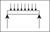 It
is called a simple uniform beam with a distributed load. This could be a bridge, a floor joist in a
warehouse or a library shelf. For now,
let’s suppose the beam is a harp neck.
To keep things simple, lets assume it is made of a rectangular blank of
hard wood, 2” thick and 6” and 23” long.
The distributed load is 900 lbs.
If you guessed the maximum strain would be in the middle, you’re
right. But just how far should it
bend?
It
is called a simple uniform beam with a distributed load. This could be a bridge, a floor joist in a
warehouse or a library shelf. For now,
let’s suppose the beam is a harp neck.
To keep things simple, lets assume it is made of a rectangular blank of
hard wood, 2” thick and 6” and 23” long.
The distributed load is 900 lbs.
If you guessed the maximum strain would be in the middle, you’re
right. But just how far should it
bend?

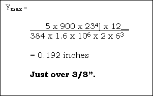
Now if we made that beam, or harp neck six
inches deep instead of four, we find it is dramatically stiffer. The maximum deflection drops to .056 inches
– less than 1/16”.
But wait a minute! Can we verify this? Does
the neck really bend down 3/8ths of an inch?
When I started stringing one of my harps, I measured the length of the
mid range strings (eyelet to bridge pin).
A few weeks later, after it had settled in, I measured it again - it had
shrunk nearly a full inch! Way more
than the math predicted.
What Happened? Was my alma mater going to ask for my diploma back? Turns out I forgot that the stress of string
tension induces strain on both of its ends.
The soundboard was bowing UP too. Whew! At least they
weren’t going to take my pocket protector and slide rule. What kind of strain do the equations predict
for the sound board?
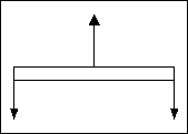 Well,
it turns there is a second loading diagram that looks suspiciously like the
sound board in cross section. Like the
last beam, the greatest deflection is in the middle, but the equations are
slightly different. Lets use it on three
different sections of the sound board.
At the top of the soundboard the string spacing (measured along the
soundboard) is about 1inch, the free span (L) is 3", and the wood is about
1/8" thick. Think of the sound
board sectionally – a piece of wood about the size of a stubby tongue depressor
being pulled by one of those little .028” nylon strings. Near the bottom, the string tension is
higher, but so is the spacing – it is closer to 1-1/4". The span can be as much as 12-16". The soundboard is 1/4" thick.
Well,
it turns there is a second loading diagram that looks suspiciously like the
sound board in cross section. Like the
last beam, the greatest deflection is in the middle, but the equations are
slightly different. Lets use it on three
different sections of the sound board.
At the top of the soundboard the string spacing (measured along the
soundboard) is about 1inch, the free span (L) is 3", and the wood is about
1/8" thick. Think of the sound
board sectionally – a piece of wood about the size of a stubby tongue depressor
being pulled by one of those little .028” nylon strings. Near the bottom, the string tension is
higher, but so is the spacing – it is closer to 1-1/4". The span can be as much as 12-16". The soundboard is 1/4" thick.
One adjustment that is important is string
tension. Remember the string is pulling
diagonally – at an angle of about 60 degrees from perpendicular (to the
soundboard) on most harps. The sine of
60 degrees is .5, the loads used to calculate deflection up (on the sound
board) are smaller than the tension on the string.
The new equations and numbers are:
Ymax =(PL4)/(48EI), I = bd3/12
|
|
Free
Span (L) |
Thick-ness (d) |
Breadth (b) |
Load (P) |
Deflection Ymax |
|
Treble |
3” |
1/8” |
1” |
10# |
0.0216, less than 1/32” |
|
Mid-range |
8.5” |
3/16” |
1 ¼” |
15# |
0.194, just over 3/16” |
|
Bottom |
14” |
¼” |
1 ½ “ |
20# |
0.4375, about 7/16” |
Now this is not a very good approximation for
the bass section. If you look down a
string band on a 36 string harp the maximum deflection is usually 8 or 9 strings
from the bottom. This is because string
ribs are attached to the pillar which is pushing down quite hard, but the
equations do come pretty close to the measured values for the top 2/3rds of the
soundboard.
One of my first designs was a harp where the bass end of the board and string band was not connected. The deflection on these harps followed the calculations pretty well down through the bass end. As I built successively larger harps I found that the strain was just too high. The adhesive at the bottom of the soundboard would start to fail and the bottom end, and would explode off the sound box with a spectacularly noisy bang.
Now, there are a whole other set of equations that one can use to calculate the maximum stress in our theoretical beam. One could use them to determine whether the beam will rupture, or just how thin they could make the sound board. This is good practice with numbers, but I have found that when my soundboards fail, they usually tear right off the harp at the edges instead of cracking in the middle (which is where the equations predict the maximum stress is). These are usually failures of the glue joint or fastening system, which has always been one of the biggest challenges when working with wood.
Necks? Well, their most common modes of failure are splitting from the underside near the treble end of the harmonic curve, or eventually twisting/tipping over (from the torque). You will find strategies on dealing with these failure modes in the Guide, Building the Lever Harp, and the online tutorial Repairing a Cracked Neck with Carbon Fiber.
Equations from
Esbach’s Handbook of Engineering Fundamentals, Beams and Bending P 4-27.
Back
to the Structural Analysis of the Folk Harp